Positioning of a Centralized Feeding System and Pipes
The installation of a Centralized Automatic Feeding System must meet a series of requirements that guarantee, in terms of the location of the machine and the pipes, the correct storage of the feed, its perfect state of preservation and its transport from the feeder to the tanks or cages through the pipes.
CENTRALIZED FEEDING SYSTEM LOCATION
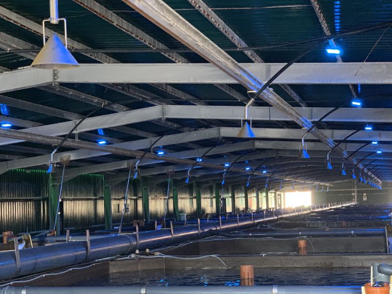
The centralized feeding system must be placed indoors, under a roof or under some element, that protects it from the rain. The silos must be refilled under a roof. If done outdoors, refilling the silos on rainy days will cause them to become damp and deteriorate, causing blockages.
- The machine’s ventilation grilles must be at least 1 m away from any wall or obstacle to allow air to circulate.
- The silos must be separated from walls or obstacles by a sufficient distance to allow for reloading of the silos and inspection and maintenance work.
- The connection cables between the two units must be protected with rigid elements to prevent damage.
PIPE INSTALLATION
Selector Matrix
- The pipes must be placed in the matrix nozzles so that the pipe enters the entire nozzle.
- If necessary, apply a little heat evenly across the entire diameter of the pipe to facilitate placement.
- If they are slightly loose, fit clamps and tighten them before the pipe cools down.
- The expansion of the pipes must be considered, so before entering the die, leave some slack in the pipe to absorb any expansion or contraction.
Aftercooler – Rotary valve
- The stainless-steel tube connecting the aftercooler and the rotary valve (on models that have one) cannot be cut. (Reducing this distance may cause blockages).
- On models that do not have a stainless-steel tube, the connection between the aftercooler and the rotary valve is made with a polyethylene tube.
Rotary valve – Tank
The recommended type of pipe for this purpose is high-density polyethylene PE 100 and PN 10 (200 Psi to SDR 11; 125 Psi to SDR 17) with UV protection.
DN | ID | Wall thickness | SDR | wall thickness |
mm | mm. | mm | mm | mm |
20 | 16 | 2 | 11 | 1.82 |
25 | 20.4 | 2.3 | 11 | 2.27 |
32 | 28 | 2 | 17 | 1.88 |
40 | 35.2 | 2.4 | 17 | 2.35 |
50 | 44 | 3 | 17 | 2.94 |
63 | 55.4 | 3.8 | 17 | 3.71 |
75 | 66 | 4.5 | 17 | 4.41 |
90 | 79.2 | 5.4 | 17 | 5.29 |
110 | 96.8 | 6.6 | 17 | 6.47 |
- The bends in the pipe should be as wide as possible. The aim is to maximize the pipe’s service life. In bends, the feed causes abrasion on the outside of the pipe, leading to wear.
- The minimum recommended radius is 2 m.
- The pipes must be unrolled and stretched until they return to their straight shape.
- Pipes should not be installed below 10 ºC.
- Pipes should be laid as flat as possible. Valleys should be avoided.
- Water can accumulate in dips due to condensation caused by the dew point temperature.
- Pipes should be placed on trays or rigid elements that keep them as flat as possible.
- If rigid elements cannot be used, a support must be placed every meter.
- Pipes must be joined using straight connectors or electrofusion sleeves (when the pipe is larger than 63 mm). Butt-welding cannot be used.
CORRECT PLACEMENT OF PIPES
INCORRECT PLACEMENT OF PIPES
Pipe cut incorrectly and not butt-welded to the nozzle.
Pipes are disordered and not secured.
Pipe poorly secured and inadequate fastenings.
Grow your business with innovative feeding systems.
Start improving your profitability today.
From land-based fish farms to offshore systems, Fish Farm Feeder develops automated solutions tailored to every environment. Our technology enhances operational efficiency, optimizes resources, and maximizes your business profitability.
